|
|
Bob's Shop Notes: |
The comic-book below will describe some techniques used here in our shop to mount these critters.
|
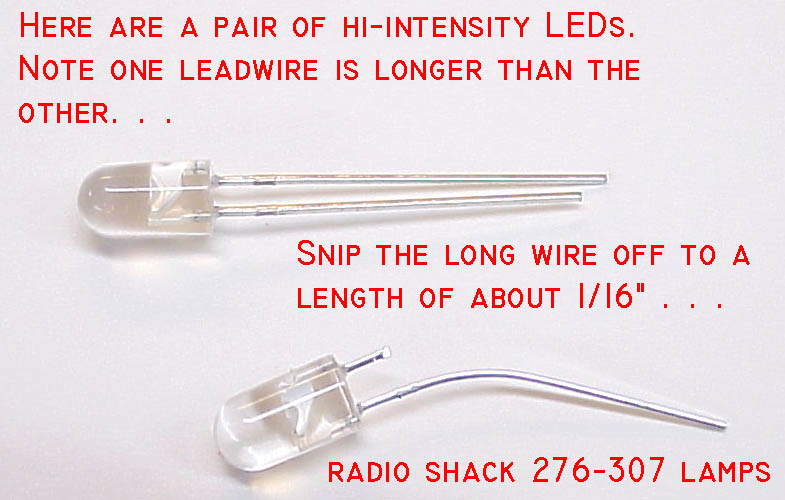
Leadwire Attachment Option 1 . . .LED's offer some really neat, solid state alternatives for illumination and annunciation. Unlike the classic filament-inside-the-glass-bulb, LEDs run cooler, they offer several colors without having to filter the light, and they will probably run the lifetime of the airplane without need for replacement. In recent years, very high light output LEDS have become available for very attractive prices. I purchased a bag of 250 high intensity red LEDs out of a surplus catalog for $25.00 . . . that's 10-cents each! The problem with LEDS is the fact that they generally supplied as a glob of plastic with two solid wire leads. You need need a robust method for both attaching leadwires -AND- mounting on your instrument panel. This document will present several variations on a theme for making both an electrical and mechanical connection to the common light emitting diode. Our first task is to attach stranded wires to the lamp in such a manner that the joint is robust and ultimately protected from stresses of installation and operation. The (+) leadwire of an LED is slightly longer than the (-) leadwire. Let's begin by clipping the longest wire down to about 1/16" of an inch. |
|
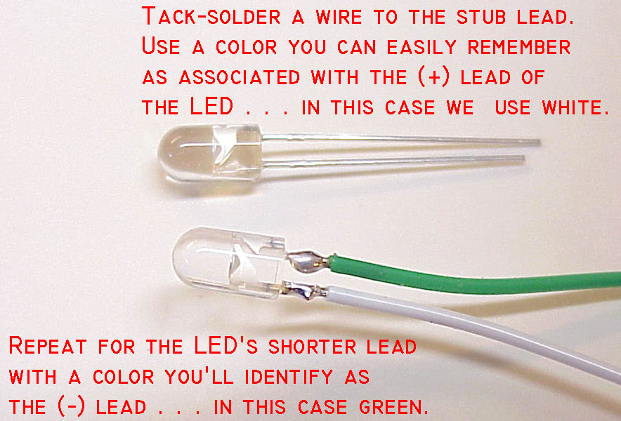
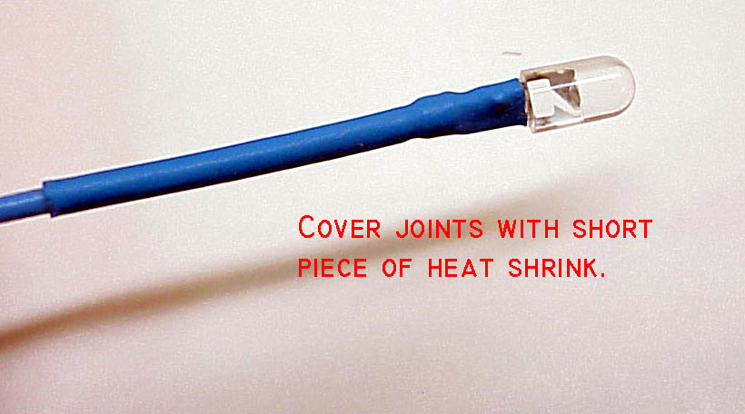
Click here for larger image. LEDs are polarity sensitive so pick different colors of wire for the two leads. In this example I used a white wire for (+) and a green wire for (-). These colors happened to be handy scraps on the bench when I built the assemblies for photographing. Red and black are commonly used for (+) and (-) leadwires. Using colors that run with common conventions will make them easy to remember. Use any other colors you like but keep track of them. Consider making these wires long enough to reach fom the indicator's roost on the panel all the way to their future attach points. It's a good idea to limit the number of connections in any wire to those NECESSARY for installation and maintenance. Strip the ends of each wire to be soldered to the LED to 1/16" and tin the exposed strands with solder. Tack solder the wire you've chosen for a (+) lead to the stub of the (+) we trimmed off above. Then cut the LED (-) lead to a 1/16" stub and tack- solder the selected (-) leadwire to the stub. What we have now is an LED with very long but very fragile leads. It wouldn't take much vibration to break these fellers off the lamp . . . but we're going to fix that. At this point, you might wish to cover up these joints with short segments of small heat-shrink. Heat shrink will offer some relief from bending strain on the finished assembly leadwires but if you don't have any really small heatshrink, don't worry about it. |
|
|
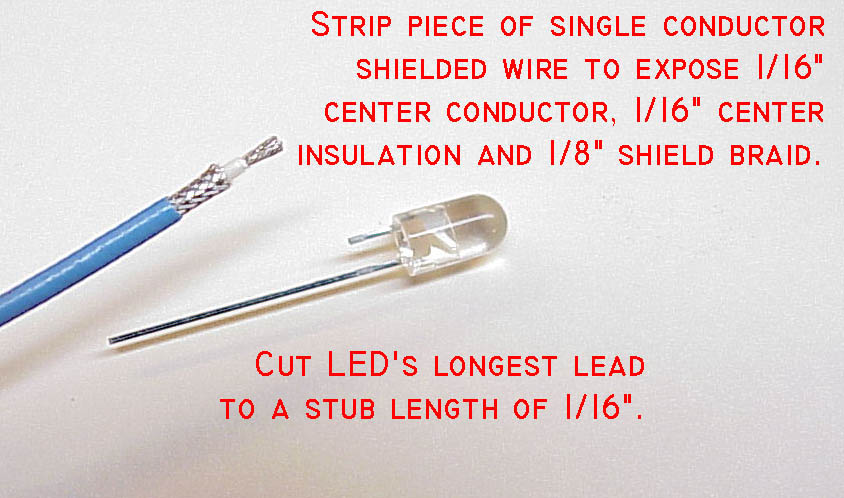
Click here for larger image. One of my favorite ways to extend connections on and LED is with shielded wire. NOTE: There is no performance advantage for using shielded versus un-shielded wires, there is only a mechanical convenience which will become apparent to you. I begin by preparing the end of the shielded wire to expose 1/16" of center conductor, 1/16" of center insulation and 1/8" of shield braid. Tin the center conductor strands with solder as shown.
|
|
|
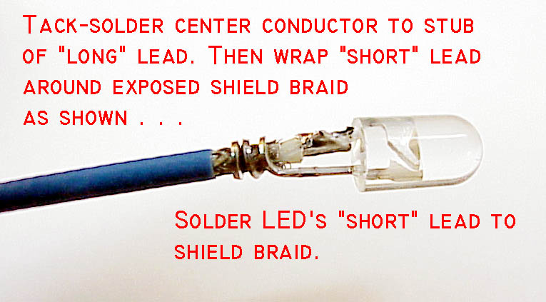
Click here for larger image. Clip the LEDs longest (+) lead to 1/16" and tack-solder the center conductor of the shielded wire to it. Hold the lamp in with the tip of needle nosed pliers so that you have a grip on about 1/8" of exposed leads right up next to the lamp's base. Wrap the LED's full length (-) lead around the shield braid as shown and solder it as well.
|
|
Click here for larger image. If you've got some 1/8 or 3/32" heatshrink handy, shrink an inch or so piece of it down over the finished joints.
|
|
|
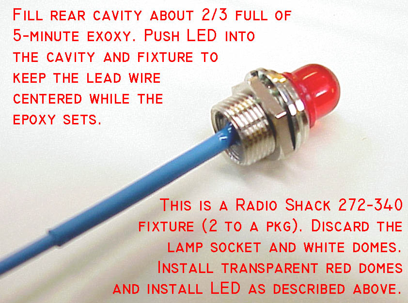
Fixture Option A . . .Here's one way to finish your LED indicator assembly. A Radio Shack 272-340 blister pack will get you a pair of lamp fixtures that come with your choice of translucent white or clear red domes. I've removed and discarded the socket for a screw-based incandescent lamp leaving us just bright metal, threaded mounting bushing and a clear red dome. Fill the fixture about 2/3 full of 5-minute epoxy and then push your new long-lead LED into the epoxy. Fixture until the epoxy sets up. Our previously fragile leadwire connections are completely enclosed and firmly supported by the epoxy. |
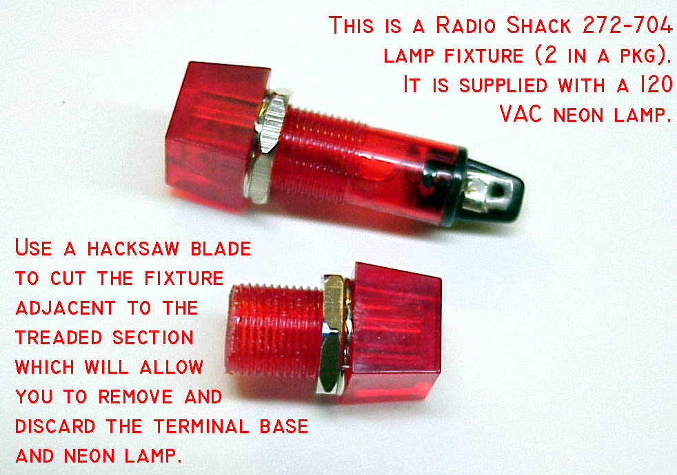
Fixture Option B . . .A Radio Shack 272-704 blister pack gets you a pair of plastic indicator lamps with neon bulbs. The assembly includes a resistor so that the 65v neon lamps can be operated from 115VAC. Use a hack-saw or hobby-saw to cut the smooth barrel portion of the fixture from the threaded portion. |
|
|
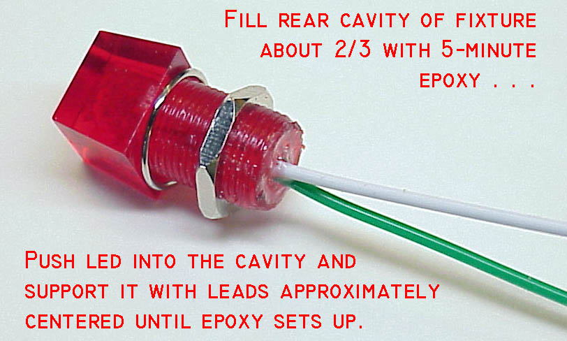
Click here for larger image. Fill the fixture about 2/3 full of 5-minute epoxy and then push your new long-lead LED into the epoxy. Fixture until the epoxy sets up.
|
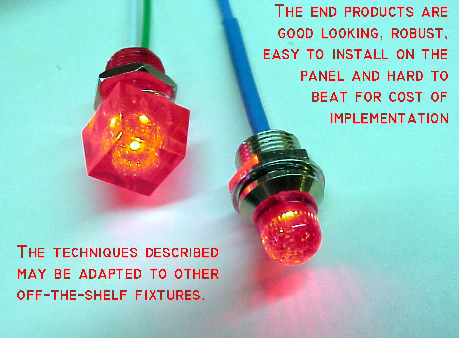
Finished Product . . .These basic techniques can be applied to many combinations of off-the-shelf lamp fixtures and LEDs. The technique is in-expensive and easy to try out for combinations other than those shown here.
|
|
 Click here to contact Bob at AeroElectric Connection Click here to contact Bob at AeroElectric Connection |